- RRS – Remote Request Substitution
- IDE – IDentifier Extension
- FDF – FD Format Indicator
- res – Reserved bit in FD frames
- BRS – Bit Rate Switch
- ESI – Error State Indicator
There are three main differences between CAN FD and Classical CAN: Bit Rate Switching (BRS); maximum size of the data payload; the coverage of the CRC. The first two of these will be identified and explained first, because these two are directly visible to, and controllable by, the systems engineer. The third difference, the size of the CRC, is largely invisible and not controllable by the systems engineer, so it will be saved for later in this tutorial.
Bit Rate Switching
In a classical CAN frame, all the data is sent at one bit rate. This can be from 10kHz up to 1MHz and is always one fixed bit rate. In CAN FD, the FD stands for Flexible Data rate. This means that two different bit rates can be used in one CAN FD frame. These bit rates are fixed for one frame and one network and cannot be changed in any dynamic way. Just like in classical CAN, a system is designed for a specific bit rate, but in CAN FD you can have two different bit rates for different parts of the frame. This feature is called Bit Rate Switching (BRS) and is enabled by a new control bit called BRS, added to the existing control bits between the CAN ID and the Data Length Code (DLC).
It is important to understand that a CAN FD network does not have to enable BRS. It is perfectly acceptable to use CAN FD at one fixed bit rate, with the Nominal bit rate and the Data bit rate at equal values. If you upgrade a network to CAN FD and use the nominal bit rate only, the physical network remains the same. A system like this would still give you two of the three CAN FD advantages; larger data payloads and improved CRC coverage. In a system that is not bandwidth limited, it would be perfectly acceptable to upgrade to CAN FD for the longer data payloads and/or the added safety and security of the improved CRC and leave BRS disabled so that no change to the physical wiring would be required.
It should be noted that all arbitration is done at the nominal bitrate. During the arbitration phase, any nodes on the network can be concurrently transmitting. If the CAN-bus layout is good enough to handle a certain nominal bitrate during arbitration, it is possible to use twice that bitrate for the data bitrate, because the physical signaling is less demanding when there is only one node transmitting.
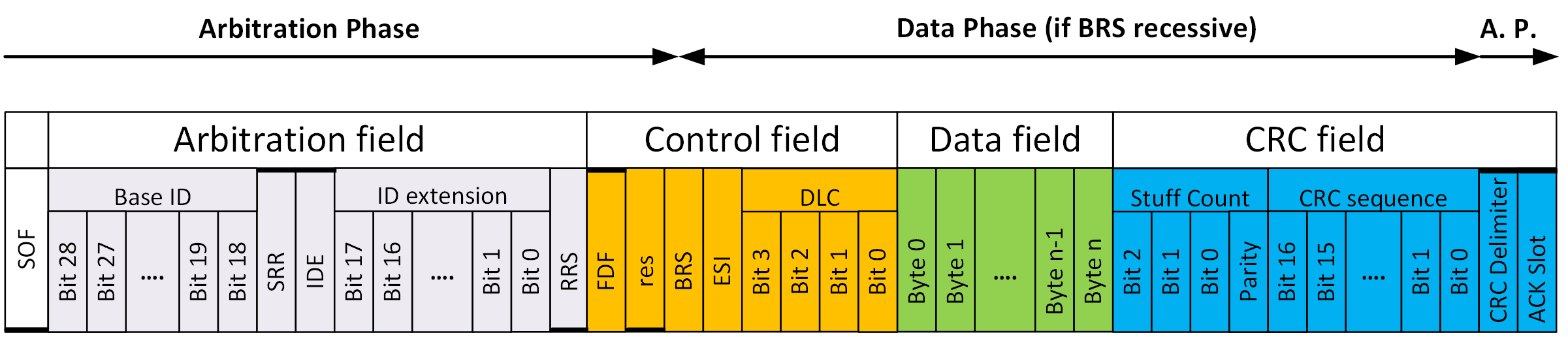
What’s called the Arbitration phase (refer to the CAN Bus Protocol Tutorial) is transmitted at the nominal bit rate , and if the BRS control bit is enabled (set to one, recessive) the Data phase is transmitted at a higher bit rate, the data bit rate . If you remember back to the CAN Bus Protocol Tutorial there are two main parts of the CAN frame, the Arbitration phase and the Data phase. In classical CAN the entire frame is sent at one fixed bit rate. In CAN FD the Data phase will be sent at a higher bit rate if the BRS bit is enabled. This higher bit rate is typically two to eight times as fast as the nominal bit rate. Nothing within the CAN frame indicates what the bit rates are. Just like in classical CAN, the bit rate is fixed as part of the system design, and all devices on the bus must know it before transmitting and receiving data. It’s just that with CAN FD you must know the nominal bit rate and the data bit rate if BRS is active.
Figure 2 above shows an Arbitration phase at a nominal bit rate that is 1/4 th that of the data bit rate. This also shows that the change in the bit rate takes place during the transmission of the BRS bit. The red arrow in Figure 2 shows the place where bit rate switching takes place.
Figure 3 ( https://www.picotech.com/ for oscilloscope information)
Figure 3 shows an oscilloscope trace of a CAN FD frame with sixteen data bytes, and a data bit rate that is eight times as fast as the nominal bit rate. In this example the bits of the arbitration phase are easy to see because they are transmitted at the nominal bit rate. A measurement of the nominal bit rate is provided in the data box in the upper center of Figure 3. The two vertical dashed lines, on each side of the sixth dominant bit in the frame, are used to measure the time duration of the bit. This measurement indicates 2 μs, so the inverse of this value gives us 500 kHz, the nominal bit rate of the frame. On the right side of the scope trace, the data bits are difficult to distinguish because they are being transmitted at eight times the nominal bit rate, or 4Mbps in this example. The last bit on the right is easy to see because this is the Acknowledge (ACK) bit, and it is transmitted after the bit rate is switched back to the nominal bit rate. The function of ACK and the bits that follow are identical to that of classical CAN, and this is described in the CAN Bus Protocol Tutorial.

Figure 4 ( https://www.picotech.com/ for oscilloscope information)
Figure 4 shows the same trace as Figure 3, but with the bit measurement now around a data bit transmitted at the data bit rate. The result of this measurement is 249.9 ns. Rounding this off to 250 ns gives us a data bit rate of 4 MHz. It is interesting to note the gray indicators just above Data – 02 and Data – 03 in the middle right side on Figure 4, showing the location of stuff bits. See Bit Stuffing in the CAN Bus Protocol Tutorial for a full explanation of Bit Stuffing.
Data Length Codes up to 64 bytes of data
Classical CAN frames can transmit between zero and eight bytes of data in the Data phase. Eight bytes is the maximum amount of data, sometimes referred to as the maximum data payload, in a Classical CAN frame. CAN FD increases this maximum payload to sixty-four (64) bytes. This significant increase in data payload enables CAN FD to be so much more efficient than classical CAN. There is one catch with this increase. In both classical CAN and CAN FD there are four control bits, called Data Length Code (DLC), that indicate the size of the data payload. The first eight bytes of data are mapped one-to-one to the DLC value, so the DLC directly indicates the number of data bytes in the data phase if there are zero to eight bytes of data. When you get above eight bytes of data in the frame, you must use a standard size frame, and the size is no longer directly mapped to the DLC value on a one-to-one basis. The table below will make this clear and shows the relationship between DLC and the size of the data payload for both Classical CAN and CAN FD.
The Logic Behind CAN FD
You might be asking yourself “How can you just turn up the bit rate in CAN FD and not introduce problems?”, or maybe “If you can turn up the bit rate in the Data phase, why don’t you just turn up the bit rate for the whole CAN frame?”. These are the logical questions to ask when presented with this information. The timing restrictions associated with the Arbitration phase of the CAN FD frame are different and more restrictive than those associated with the Data phase. This is because during arbitration there could be multiple devices transmitting on the network. It is only during Arbitration, and the Acknowledge (ACK) bit, that multiple physical devices can transmit simultaneously. It is this simultaneous transmission, possibly from devices at different ends of the network, that limits the nominal bit rate to the lower value of the arbitration phase. After arbitration is finished, only one device is still transmitting, and a higher data bit rate can be used. After the data and the Cyclic Redundancy Check (CRC) have been sent, the transmitter will switch back to the nominal bit rate, and the ACK bit will follow. It should be noted that the ACK-bit is actively transmitted by all units except the sender of the CAN-frame. This causes the same physical signal complexity as during the arbitration phase, which demands the use of the Nominal bitrate.
Increased requirements on the Physical Layer
Because of the faster data bit rate in CAN FD, the proper physical design of the CAN network is more important. Achieving the maximum data bit rate depends on the quality and consistency of the physical network design. It is true that at any given bus speed, CAN FD will run the same as classical CAN, and no change to the physical network is required. It is when you start increasing the data bit rate that you must look more closely at some physical parameters of the network. The physical parameters that affect the maximum bit rate of a CAN FD network are:
- Oscillator quality
- Fundamental oscillator frequency
- Bit timing register configurations
- Length of the network cables
- Cable quality and layout
- Selected CAN FD driver
- EMC filters
Each of these parameters should be considered during the network design phase and during selection of the data bit rate.
The bit-register configuration is calculated from the CAN-bus layout and the delay, oscillator tolerance, and physical location of each installed node. In other words, this bit-register configuration demands system knowledge for a perfect setting in each installed node. Classical CAN is very robust, and most systems are not very demanding, which allows for a very relaxed bit-register configuration.
In CAN FD, the bitrate switch is in the sample point, and this switch must be done concurrently in all installed units (at the sample point in the nominal bit). This demands that all installed units have the same location of the sample point in the configuration of the nominal bitrate of the CAN FD frame. In Classical CAN, a system would survive sample point variation up to 20%. The problem is that 20% phase shift in the nominal CAN-bit of CAN FD will be 40% in the data-bit for a data bitrate that is only twice the nominal bitrate. For this reason, it is necessary to secure that all installed units have a common setting of the sample point in the nominal bitrate before the bitrate switch is used. Similar problems exist when switching from data bitrate to nominal bitrate, but in this case the phase shift is scaled down, and is therefore less problematic.
It is important to stress the significance of bit timing register configurations because the most common network problems are a result of mistakes made in configuring these registers. If you are using CAN FD in specific applications that are well documented, you will find that the nominal and data bit rates are specified in the standard. Other things that are specified for each phase of the CAN FD frame are the Synchronization Jump Width, Sample Point, Bit Rate Prescaler, as well as other timing and bit quanta parameters. This takes much of the complexity out of configuring your controller, simply because you must follow the standard. If one of these parameters differ from other nodes in the network, such as the Sample Point, you will get bit errors.
Helpful Tools
CAN FD Bit Timing Calculator
Calculate all possible sets of CAN FD bus parameters for a given input frequency and a given bus speed.
Different types of CAN and CAN FD frames
When CAN was first introduced by Bosch in 1986 it was introduced with an eleven-bit identifier. At the time we referred to this as Standard CAN . A few years later a twenty-nine-bit identifier was introduced, and we called this Extended CAN . (see Standard vs. Extended CAN in CAN Messages section of CAN Bus Protocol Tutorial)
When CAN FD was incorporated into the ISO 11898 standard in 2015, two new frame formats were introduced, and the common way of referring to different frame formats was changed. Four new acronyms came into existence and started to be used by other CAN related standardization bodies as well. These acronyms are listed and defined here:
CBFF – Classical Base Frame Format: Original CAN with an 11-bit ID and 0 to 8 bytes of data.
CEFF – Classical Extended Frame Format: Original CAN with a 29-bit ID and 0 to 8 bytes of data.
FBFF – FD Base Frame Format: CAN FD with an 11-bit ID and up to 64 bytes of data.
FEFF – FD Extended Frame Format: CAN FD with a 29-bit ID and up to 64 bytes of data.
From this list it is easy to figure out that CAN FD can use either the eleven-bit identifier or the twenty-nine-bit identifiers. As with classical CAN, the identifier can be used to identify the data frame, or it can be used for some other purpose. This is dependent on the high-level protocol and is not defined in ISO 11898. Regardless of what the identifier is used for by the high-level protocols, it will always be used for arbitration because of how bit-wise arbitration works, as defined in ISO 11898 (see Bus Arbitration and Message Priority in CAN Bus Protocol Tutorial).
A look at the new control bits in CAN FD
The control bits that are transmitted after the identifier in a CAN FD frame are listed below. Some of these control bits are the same as those in a classical CAN frame, whilst some have changed functions and names. Some bits are completely new and didn’t exist in classical CAN. These control bits are not something that most users of CAN FD will need to worry about. If you’re working with a CAN FD application using a high-level protocol, you may never see these bits. Some of these bits are used by the application to format the way different parts of the CAN frame are interpreted, and are never actually displayed themselves. The CAN FD controller and/or the driver/configuration software will handle these bits properly. System designers who are working at the physical and datalink levels are the ones who will need these details. It is presented here in an abbreviated format to encourage a better understanding of the CAN FD frame structure.
Substitute Remote Request (SRR)
This bit is only defined for Extended frames (IDE=1) and has a different use in the Base frame when IDE=0. For the 29-bits frame formats CEFF and FEFF where IDE=1, this bit substitutes the RTR-bit in CBFF and the RRS-bit in the FBFF. This bit is always sent recessive (SRR=1) for both frame formats. CAN FD receivers will accept SRR=0 without triggering a form error.
IDentifier Extension (IDE)
Unlike the bits I have described above, the IDE bit is always called the same thing, and it is always transmitted in the same time slot. For both the CBFF and FBFF, the IDE bit is dominant. That means for any Base Frame Format, that is any frames with an eleven-bit ID, IDE is dominant. For both CEFF and FEFF the IDE bit is recessive. That means for any Extended Frame Format, that is any frame with a twenty-nine-bit ID, IDE is recessive.
Remote Request Substitution (RRS)
Both CBFF and CEFF support RTR (Remote Transmission Request) which is indicated by a recessive bit (RTR=1) after the last ID bit. When an ordinary data frame is sent, this bit will be sent as dominant (RTR=0). In CAN FD remote request is not supported, and all CAN FD frames are data frames, which for Classical frames are indicated by dominant (RTR=0) bit. To indicate the different use in the CAN FD frames, this bit is named Remote Request Substitution (RRS). The RRS-bit is always sent dominant (RRS=0) because a CAN FD frame is always a data frame. CAN FD receivers will accept RRS as recessive (RRS=1) without triggering a form error.
FD Format indicator (FDF)
This is the bit that distinguishes between classical CAN and CAN FD frames. It is dominant in the classical CAN frame formats (CBFF and CEFF), and recessive in the CAN FD frame formats (FBFF and FEFF). The FDF bit is not always transmitted in the same time slot. In the Base frame formats (CBFF and FBFF) the FDF bit is transmitted in the control field just after the IDE bit. Because the arbitration field is extended in frames with 29-bit identifiers (CEFF and FEFF), the FDF bit is transmitted after the RTR or RRS bits respectively in extended frame formats. This keeps it in the control field, so it is never included in arbitration.
Reserved bit in FD Frames (res)
This bit is only present in CAN FD frames and is always transmitted as dominant. It is reserved for future use and will most likely be used in CAN XL (the subject of a later protocol tutorial). Since it is transmitted as part of the control field it is not used in arbitration. It is interesting to note that it is called the r0 bit only in classical extended frames (CEFF), but still transmitted in the same state as dominant. The reason for the naming differences, and really for the existence of this bit, is for backward compatibility with previous versions of ISO 11898.
Bit Rate Switch (BRS)
This is a bit that is completely new to CAN FD, and did not exist in classical CAN. One of the big advantages of CAN FD is that the bit rate can be increased up to 8 Mbps after the arbitration field is transmitted. BRS is part of the control field, always transmitted just after the res bit. It indicates whether the bit rate is going to stay the same or switch up to a faster rate. The arbitration field is always transmitted at the nominal bit rate, and if BRS is recessive the bit rate will switch up to a higher data bit rate at the sample point of the BRS bit. So BRS is unique; it is the only bit whose state determines a timing shift at its own sample point. If BRS is sampled as recessive the bit rate will switch to the data bit rate, and sample points will have to switch accordingly. If BRS is sampled as dominant, the bit rate will remain the same for the rest of the CAN FD frame. Figure 2 is a representation of the control field that clearly shows the location of the sample point of BRS and the resulting change in bit timing from an active BRS.
Error State Indicator (ESI)
This is also a new bit only used in CAN FD. The ESI bit is used by a CAN FD node to indicate that it is in an error active state. By transmitting ESI as dominant, a node is indicating that it is in the error active state, and by transmitting it as recessive the same node indicates an error passive state. ESI is always transmitted in the control field, just after BRS. This means it is the first bit to be transmitted at the data bit rate in all CAN FD frames with BRS enabled.
If you want to learn more about error states, please see CAN Error Handling in the CAN Bus Protocol Tutorial.
CRCs of 17 and 21 bits, and increased error detection coverage
In most communication protocols there is a block of bits, usually transmitted after everything else in the frame, called the Cyclic Redundancy Check (CRC). The CRC is not unique to CAN or CAN FD, it is used in many digital communication protocols. There is plenty of good information out there on the concept of CRCs, including entire books written on the concept alone. Classical CAN uses a 15-bit CRC and doesn’t include the stuff bits. CAN FD uses either a 17-bit CRC for data fields up to and including 16 bytes, or a 21-bit CRC for data fields 20 bytes and over. CAN FD also includes the stuff bits in the CRC calculation, and adds a 3-bit stuff count to be transmitted at the beginning of the CRC. Because of the larger data phase available in CAN FD, these changes are required to give CAN FD comparable error detection capability to that of classical CAN.
The CRC Delimiter is transmitted just after the last bit in the CRC sequence. When a CAN FD node reaches the sample point of the CRC delimiter, it switches from the data bit rate back to the nominal bit rate. This change can be seen in Figure 3, where the recessive CRC delimiter is a little longer than the data bits, and the dominant Acknowledge bit is displayed at the nominal bit rate.
Acknowledge Bit
The Acknowledge (ACK) bit is shown furthest to the right in Figure 5. It’s shown as recessive, although if you look at Figure 3 you see it as the last dominant bit in the frame. It is shown as recessive in Figure 5 because it is transmitted as recessive by the node that has transmitted the frame. It is the other nodes, all receivers on the network, that drive the ACK bit to dominant, just like in classical CAN. It only takes one node to drive the bus dominant, so what the ACK bit tells the transmitting node as it finishes transmitting a frame, is that at least one receiver has confirmed reception of the frame.
Summary
As stated in the first paragraph, we’ve targeted test engineering with the level of detail and the subjects covered by this document. We’ve talked about the two changes that make CAN FD a higher performance protocol: Bit Rate Switching and the increased maximum size of the data payload. Bit Rate Switching allows the use of a faster bit rate during the data phase of the transmission. This faster bit rate is only possible if the physical network is designed to support it. Increasing the size of the data payload can increase the efficiency of transmitting larger blocks of data, but can also decrease real time performance if not accompanied by Bit Rate Switching. These are important changes to understand for the test engineer who must recognize and test CAN FD. For a system engineer who wants to customize the performance of a network to suit a specific application, a deeper level of understanding will be required. A deeper level of understanding will also be required for a physical network designer who wants to get all available performance out of a network. Look for future publications from Kvaser to address both subjects, and feel free to send questions to support@kvaser.com if there is anything we can help you with.